Rotary Motors
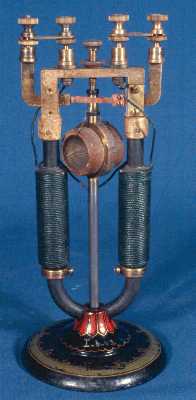
   Rotary motors of the type shown at the right were designed by Charles Grafton Page and described by him in the American Journal of Science in 1837. In the various editions of Daniel Davis's Manual of Magnetism it is described as a "revolving electromagnet."

   The revolving electromagnet spins between the poles of a permanent magnet. The current is fed to the electromagnet by a "pole changer", or commutator, invented by Page. 

   The unmarked example at the right is in the collection of the University of Cincinnati and follows the original design quite closely.


    This example of a Page-type motor is in the collection of the National Museum of American History of the Smithsonian Institution. Judging from the painted decoration on its cast-iron base, it likely dates from about 1900. Note that the permanent magnet has been replaced by an electromagnet. As is customary, the wire windings setting up the static magnetic field are painted green. 

   An apparatus, similar apart from details of the base, is listed at $9.75 in the 1916 catalogue of the L. E. Knott Apparatus Co. of Boston. The equivalent apparatus with a permanent magnet cost $8.50.

   At one time this apparatus was at Vassar College in Poughkeepsie, New York. 


   This Page-type motor in the collection of the National Museum of American History at the Smithsonian Institution. An attached tag noted, when I took the picture in June 1979, that the apparatus was made by Ritchie of Boston, but the 1860, 1869 and 1881 Ritchie catalogues in my collection show the form of Page motor at the top of  this page. 
   The apparatus at the left is all that remains of a Page-type motor at Denison University. It was likely made by a student in the advanced physics course in the years from 1880 to 1910. Both the magnet and the rotor were missing when I discovered it. The outline of the U-magnet I added when I put it in an exhibit of early physics teaching for Denison's sesquicentennial celebration in 1983. The pole-changer leaves are still in place. The rotating shaft ran between the brass plate at the center of the base and the center of the crosspiece, with the rotating electromagnet at the lower portion of the shaft so that it would be between the poles of the permanent magnet. 


 Return to Electric Motor Home Page | Return to Home Page